
The cookie is used to store the user consent for the cookies in the category "Performance". This cookie is set by GDPR Cookie Consent plugin. The cookie is used to store the user consent for the cookies in the category "Other. Open-collector outputs of some gates have a higher maximum voltage, such as 15 V for the 7426, useful when driving non-TTL loads. Examples of this type of gate are the 74 series. The cookies is used to store the user consent for the cookies in the category "Necessary". If any of the logic gates becomes logic low (transistor conducting), the combined output will be low. The cookie is set by GDPR cookie consent to record the user consent for the cookies in the category "Functional". The cookie is used to store the user consent for the cookies in the category "Analytics". These cookies ensure basic functionalities and security features of the website, anonymously. It is used in printer-integrated circuits.Necessary cookies are absolutely essential for the website to function properly.Used in microprocessors and microcontrollers as one of their fundamental components.

It is widely used in CMOS inverters to produce waveforms.The following are some major applications of NOT gate: The schematic diagram of the 7404 IC is shown in the following figure. The IC 7404 is a commonly available NOT IC in the market.
Transistor not gate drivers#
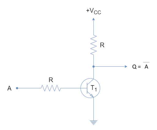
The following table gives a list of commonly available inverter ICs in TTL and CMOS logic: IC Name Logic Family Description 74LS04 TTL Logic Hex Inverting NOT Gate 74LS14 TTL Logic Hex Schmitt Inverting Gate 74LS1004 TTL Logic Hex Inverting Drivers CD4009 CMOS Logic Hex Inverter NOT Gate CD4069 CMOS Logic Hex Inverting NOT Gate 7404 NOT Gate IC When the input voltage at A is low (say 0 V), then the transistor becomes OFF, and the current does not find any path to the ground, and the entire supply voltage (+V CC) will be available at the output Y, making it high, i.e. When a high voltage (say +5 V) is applied at the input A, the transistor becomes ON, and the current flows from +V CC to the ground through the transistor, making the output low, or 0. This circuit is also known as a transistor inverter. The circuit diagram of an inverter using a bipolar transistor is shown in the following figure. The NOT gate can be implemented by using a bipolar junction transistor (BJT). This way the above shown circuit realizes the inverter logic operation. This time no current will flow through the lamp, making it turned off, i.e. A = 1, the current follows the path through the switch, as it provides a short-circuited path with low resistance. A = 0, the current through the circuit follows the path from the battery to the lamp and comes back to the battery. This realizes the NOT operation as follows: The circuit consists of a battery, a switch, and a lamp. The electrical equivalent circuit of the NOT gate is shown in the following figure. Where A’ or (A bar) denotes the complement of the input signal. The Boolean function of a NOT gate is given below. Boolean Expressionīoolean expression is a logical function that provides a mathematical relationship between the input and output of a logic. Input (A) Output (Y = A’) 0 1 1 0įrom the truth table, it is clear that the NOT gate performs the inversion operation by converting 0 into 1 or 1 into 0. The truth table of the inverter logic is given below. The truth table is a table of input and output that shows a relationship between them and is used to analyze the operation of the logic.

It denotes a complement/inversion of the input signal. In the logic symbol, the bubble at the right corner of the triangle is called the inversion bubble.

The basic logic symbol of a NOT gate is depicted in the following figure. Therefore, it operates as an inverter, i.e. It gives a HIGH (Logic 1) output when its input is LOW (Logic 0), and it gives a LOW (Logic 0) output when its input is HIGH (logic 1). In digital electronics, the NOT gate has a single input and a single output. The NOT or inverter gate gives a HIGH (Logic 1) output when its input is LOW (Logic 0), and it gives a LOW (Logic 0) output when its input is HIGH (logic 1). In digital electronics, the NOT gate is a basic logic gate consisting of a single input and a single output. When no voltage is present on the input, the. If the input of the NOT gate is 1, then the output is 0, and vice versa. NOT gate can be realized through transistor.The input is connected through resistor R2 to the transistors base. The NOT gate is also known as the inverter gate.


 0 kommentar(er)
